Use Of Alternative Fuels Is Spreading Around The World As Part Of Global Efforts To Reduce The Carbon Intensity Of Cement Production. But Alternative Fuels Are Not A Homogenous, Easily Handled Product. Cement Products Talked To A Number Of Experts About The Practical Issues Involved In Moving And Storing These Fuels.
by Jonathan Rowland
Alternative fuels (AF) are a hot topic in the cement industry and have been for some time. They are a recognized pathway to reduce the carbon emissions intensity of cement production. The technology for their adoption is also well proven with thermal substitution rates (TSR) of up toward 100%. AF also offer opportunities to control fuel costs and reduce reliance on globalized energy markets: benefits that now seem more pressing than ever.
What Is an Alternative Fuel?
AF – also known as secondary fuels – are “selected waste and byproducts, with recoverable calorific value, that can be used as fuels in a cement kiln, replacing a portion of conventional fossil fuels, such as coal,” explained Dirk Lechtenberg, managing director, MVW Lechtenberg & Partner, a Duisburg, Germany-based consultancy and expert in the use of AF in the cement and related industries. Often, but not always, these materials “can only be used after pre-processing to provide tailor made fuels for the cement process.”
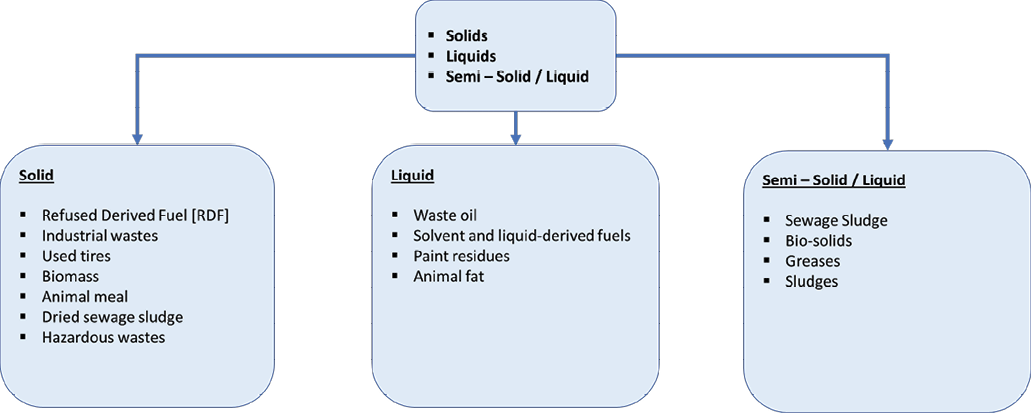
AF comes with a range of designations (e.g., SRF, RDF, TDF etc.) and trade names (Climafuel, Subcoal etc.). Most of these are simply “general paraphrases for AF that are either waste- or biomass-derived,” continued Lechtenberg. However, the actual range of materials that can be used as an AF in the cement process is much broader. These can be categorized according to their physical attributes as solid, liquid or semi-solid (sludge) and according to their chemistry as either hazardous or non-hazardous to human health and the environment. Figure 1 shows a general overview of AF types; some common types of AF are described below:
- Refuse-derived fuel (RDF): solid, non-recyclable, 2D, lightweight materials such as plastics, packaging, textile, foils and foams, which have been separated from municipal solid waste streams.
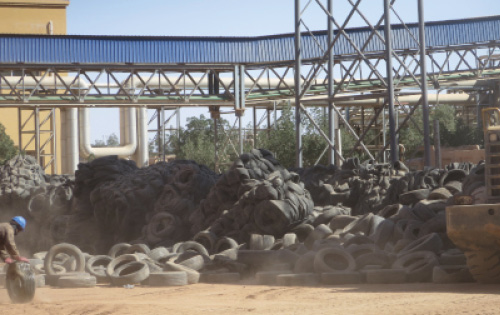
- Tires (TDF): either whole tires or shredded.
- Biomass: seasonal and determined by what is available locally. Availability and quality are therefore variable.
- Sewage sludge: a by-product of waste water treatment plants. Sewage sludge is a suitable AF only when dried.
- Animal meal: a by-product of animal rendering plants that offers stable quality and constant availability.
- Liquid waste fuels, e.g., spent solvents, waste oils and fuels, and paint, inks and coatings waste.
- Industrial sludges, such as oil sludges. These are generally ground and mixed with other coarse AF, such as wood or tire chips. They may be fed into the kiln using a concrete pump or conveyor.
“By their nature, these fuels can be variable in quality, behavior, moisture content and calorific value,” said Matt Drew, CEO/UK and group business development manager at Saxlund Group, a specialist in the design and manufacture of AF systems. Most variation is present when the fuel is “in a sorted or mixed form,” added Lechtenberg.
Variability is one of the challenges most associated with AF adoption; it also resists industry steps toward standardization because fuels are often specified on a site-by-site basis depending on the local process conditions. “Take sulfur content as an example,” said Lechtenberg. “A cement plant with a high sulfur content in its raw materials would face immense coating problems if it were to use AF with a high sulfur content. On the other hand, the raw materials at a neighboring plant contain less sulfur; this plant can therefore cope with higher sulfur levels in its AF.”
“The cement producer has to consider the chemical composition of AF, as these fuels can lead to excessive chlorine or sulfur in the combustion gases, which will lead to issues with degradation of the refractory lining in the kiln and calciner, and issues with cement quality,” added Drew. The variable nature of AF also often makes them “difficult to convey, store, discharge and accurately dose into the fuel stream,” he continued. It is now to the handling and storage of AF that we will turn to for the remainder of the article with a focus on solid AF.
Handling Alternative Fuels
“Traditional solid fuels, such as pulverized coal, have free flowing properties and are relatively easy to handle,” said Saxlund Group’s Drew. “In contrast, AF tend to be non-free flowing and prone to bridging in hoppers. Some fuels can also be sticky. This all makes the fuel difficult to handle and requiring of more specialist handling technology. In addition, many projects we work on require the fuel system to be fully automated and dust tight, to reduce emissions of waste materials into the environment.”
It is a point echoed by the materials handling experts at both U.S.-based Martin Engineering and Di Matteo Group, Germany.
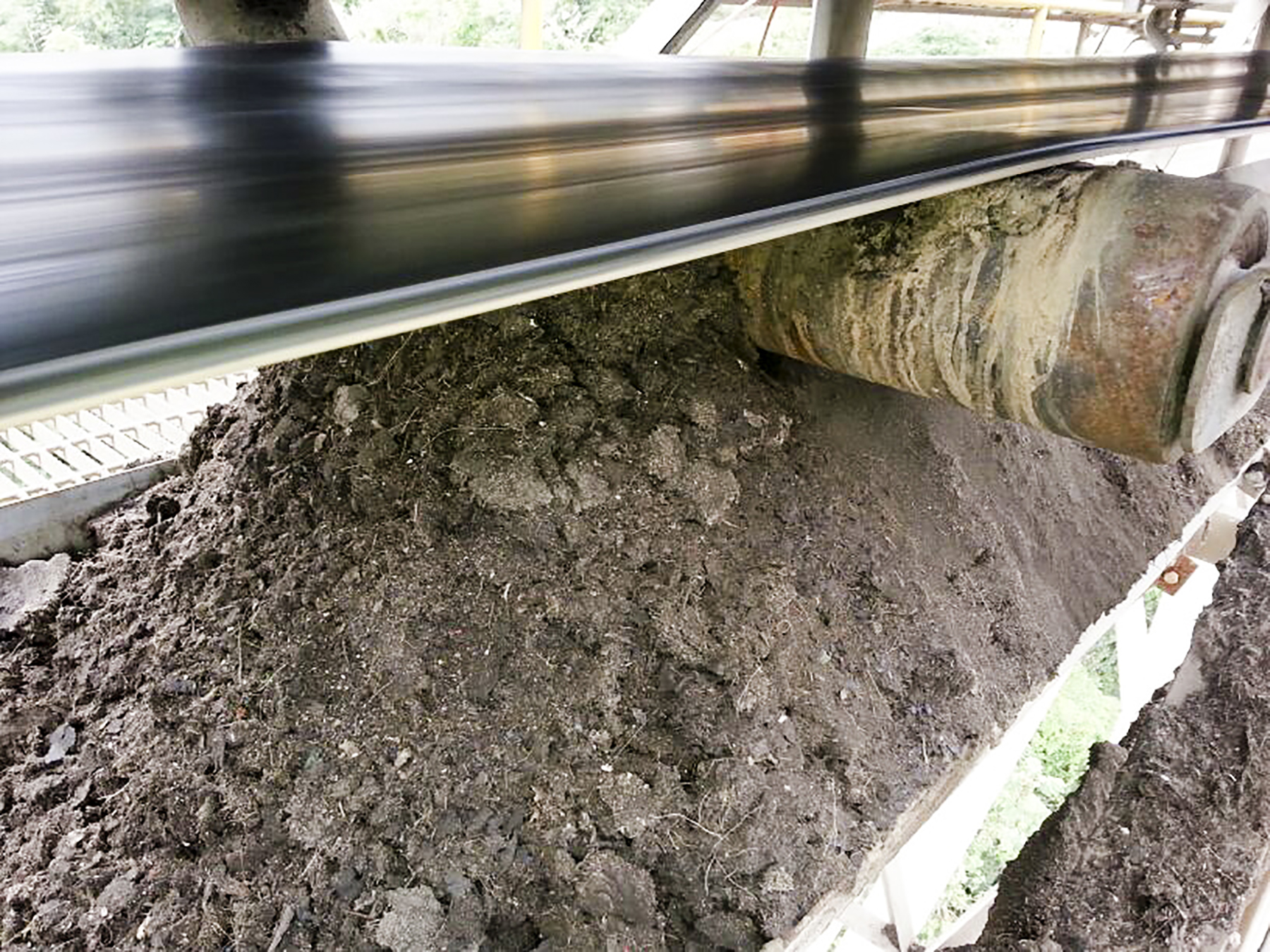
“Most of our experience with AF has been with biomass in some form, such as wood chips and sugar cane bagasse,” Alan Highton, national sales manager for wear components, Martin Engineering, told Cement Products. “One of the key differences between these materials and fossil fuels is their flow characteristics. Efficient material flow is a critical element of dry-process cement manufacturing, and accumulation or blockages can put a choke hold on a plant’s profitability. Hang-ups in storage systems and build-up in chutes and process vessels can impede material movement, causing bottlenecks that interfere with equipment performance and reduce process efficiency. Poor material flow also raises maintenance expenses, diverting manpower from core activities and, in some cases, introducing safety risks for personnel.”
“Typically, the chemical, mechanical and thermal characteristics of AF streams vary enormously over time, especially since, in most application scenarios, different suppliers and preparation plants are involved in order to provide enough material for a 24/7 feeding,” explained Dr. Luigi Di Matteo, Di Matteo Group CEO. As a result, it is necessary to “select and design all the handling equipment according to the specific bulk material properties of the utilized fuel streams.”
To assist cement customers in this, Di Matteo Group has invested in a pilot plant at its German headquarters where it tests and verifies all pieces of equipment for a specific fuel supply chain. “We can therefore reduce any kind of material related risks for investment in AF installations,” added the company head.
In addition, “many cement manufacturers are surprised by the amount of possible impurities within the AF materials streams,” continued Di Matteo. These include both metallic and mineral components that “can cause problems within the combustion process and lead to undesired downtime.”
Such contaminants also pose an issue for material handling systems. “You can and do get many impurities in the fuel,” agreed Drew. “This means that for many systems you need additional fuel processing, such as oversize and ferrous metal removal, otherwise this can lead to blockages of conveyors and pneumatic conveying lines.” Such screening is “most prudently performed immediately after the AF discharge from the storage area,” added MVW Lechtenberg & Partner’s Dirk Lechtenberg.
Conveying Alternative Fuels: Some Considerations
“The selection of conveying method will factor in a range of parameters including volume, distance, bridging heights, product characteristics (moisture, insert material content, stickiness), and climatic conditions,” continued Lechtenberg.
Take the first of these parameters: volume. “AF will often have a much lower bulk density and calorific value than coal,” explained Drew. “For example, RDF has a typical bulk density of 150 kg per cu. meter and a calorific value of 12 to 22 MJ per kg, whereas pulverized coal has a bulk density of 500 kg per cu. meter at a calorific value of 25 to 35 MJ per kg. To replace 1 metric ton of coal with a volume of 0.56 cu. meters thus requires 1.6 metric ton of RDF with a volume of 10.8 cu. meters. This significant difference must be considered for the conveying and storage capacities of the equipment.”
There are three general options:
- Pneumatic conveying.
- Mechanical conveying.
- A combination of the two.
Pneumatic conveying “has proven itself many times over,” said Lechtenberg. “It is used for solid powdery and fluffy materials, with moisture content of about 10%, over conveying distances up to about 200 meters. It provides simple enclosed transportation around edges and vertically, and there are no fuel spillages. It also requires comparatively low investment.”
On the downside, materials with higher moisture contents will tend to agglomerate in pneumatic systems and cause blockages. Pipes are also susceptible to wear, particularly around bends (although this can be mitigated by designing large radius bends with wear protection). In addition, “pulsating of the conveying air can occur as a result of worn airlocks, and false air penetration is also problematic,” according to Lechtenberg. A final consideration is energy consumption of the compressors and blowers, which can be “significant,” the consultant concluded.
Mechanical conveying includes both chain and pipe conveyors. It is more suitable “for longer conveying and for coarser particle sizers – e.g., shredded waste-derived AF for the kiln inlet or calciner,” said Lechtenberg. Conveyors should also be “enclosed or covered with easily-cleanable transition idlers and pulleys to prevent spillage of fuels particles and to protect the AF from weathering.”
Avoiding Material Build-Up When Using Biomass
Even a “well-designed process can experience materials build-up,” said Highton of Martin Engineering. “Changes in process conditions, materials or climatic conditions (weather) all have an effect on material flow, and even small amounts of accumulation can quickly grow into a serious blockage. These blockages may lead to spillage, and accumulations of some AF are susceptible to spontaneous or external combustion sources. Others may accelerate corrosion of the structure and conveyor components.”
The impacts of build-up can therefore be severe and include:
- Lost production.
- Increased maintenance costs.
- Wasted energy consumption for repeated restarts.
- Increased safety risks due to more man-machine interactions.
Highton recommends a “proactive approach to fugitive material control and housekeeping” to mitigate these risks. This begins (as always) with the design of the materials handling system. “The most effective way to manage the challenges of using biomass fuel is to design the material handling system around the physical properties of the intended fuel. So transfer chutes, settling zones, support cradles, belt sealing, and other components would be engineered according to the specific flow characteristics of the fuel.”
Cement production rarely takes place in an ideal world, however. “Most cement producers will use existing systems to move the new type of fuel, which can require some retrofitting,” Highton continued, while designing a conveyor and chute work to handle every material situation is “virtually impossible.” More realistic solutions include the use of modular components and flow aids.
“Modular components can be engineered to handle specific flow properties,” continued the Martin Engineering expert. “These critical parts, such as transfer chutes with specific flow angles or settling zones of appropriate height and length, can then be retrofitted into an existing system, thus avoiding the need to replace large or complete sections of equipment.”
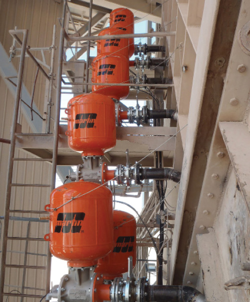
Flow aids are components that promote the clean transport of materials through a chute or vessel, and include:
- Rotary and linear vibrators.
- Air cannons and aeration devices.
- Low friction linings.
- Special chute designs.
“These systems can be combined in any number of ways to complement each other and improve performance,” said Highton. Correct engineering design is needed, however, to ensure the flow aids themselves do not impinge performance. “Because they will affect a conveyor’s loading, flow aid devices can also impact spillage and dust. And if not properly managed, accidental or intentional breakdown of build-up can produce surges, which result in overloading, spillage and belt mis-tracking.”
“By designing active flow aids into a conveying system, the operation gains a level of control over the material that cannot be obtained with static approaches (such as low-friction liners) alone,” concluded Highton.
Weighing and Dosing Alternative Fuels
Weighing is “critical to ensure feed consistency,” explained Lechtenberg: in many countries it is also obligatory. This would traditionally – and still commonly – be carried out using volumetric weight calculations. But volumetric weighing of AF is “inaccurate due to the various specific qualities of waste-derived fuels.” A more precise alternative is gravimetric weighing.
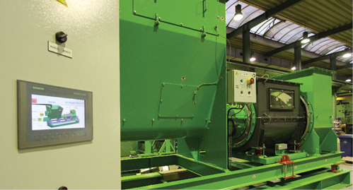
When it comes to dosing, three technologies are widely used: weigh belt feeds, rotary weigh feeders, and screw weigh feeders. While the former two are adequate when dosing fluff-like AF at lower volumes, screw weigh feeders, such as the ODM-WeighTUBE from Di Matteo Group, offer benefits when dosing larger volumes of material and can include an agitator inside the dosing bin to prevent material agglomeration.
“It is often the case that the task of AF handling is underestimated and non-adequate equipment is used,” explained Di Matteo. This is never ideal, and nowhere more so than the feeding system. “When it comes to the critical task of gravimetric dosing, it is vital to consider adequate equipment. This was the impetus behind the development of the ODM-WeighTUBE, which we designed specifically to meet all the requirements for precise and robust dosing of AF streams with volatile characteristics.”
Storing Alternative Fuels
The main objectives of storage of both traditional and AF are to:
- Protect material from the weather.
- Protect the environment from material leakage.
- Provide capacity for downtimes.
- Mix and homogenize different mass flows.
The storage of AF poses some unique challenges; however, one of the most difficult relates to calculating bulk density. Although basically constant in fossil fuels, this is variable with AF.
“The definition of actual bulk weight frequently causes great problems when designing AF storage,” said Lechtenberg. “The bulk weights of mixed waste-derived AF in particular can vary widely, due in part to the composition of waste material content, and partly due to the moisture content. In addition, the bulk weight can change in storage due to increased self-compaction caused by increasing layer depth and storage residence times.”
Lechtenberg provided bulk densities of AF and fossil fuels with the following general guidelines:
- The bulk weight of AF is approximately 250 to 300 kg per cu. meter.
- The bulk density of coal is between 700 to 1100 kg per cu. meter.
- The bulk density of heavy fuel oil (HFO) is 800 to 1000 kg per cu. meter (@15°C).
Another challenge is the fact that AF are often received in various qualities and quantities, in a range of forms, and from different suppliers. “It is advisable to keep the different fuels separate, until their suitability for mixing has been confirmed by analytical evaluation,” said Lechtenberg. “After clearance has been given for usage, homogenization should take place. The rule ‘first in – first out’ has to adhere to.”
Storage strategies for AF can also differ from those used with fossil fuels, which are traditionally delivered in bulk and stored for long periods. In contrast, AF may be delivered on a just-in-time basis. This is often the “cheapest option,” noted Lechtenberg, “but reliable 24/7 supplies have to be guaranteed, which is not easy to achieve, or the plant must have some form of downtime storage capacity on which to draw at weekends, during maintenance or technical problems.”
A final important point: the storage of AFs has to be pursuant with the substitution volumes. Increase the TSR and the storage capacity must follow suit.
Designing and Procuring an Alternative Fuels Handling or Storage Solution
Initial considerations when designing and procuring an AF handling or storage solution should include:
- What is the target TSR?
- What types of fuel are being considered and in what mix? – What waste streams are available locally?
–Non-hazardous – can be accepted directly from the waste generator.
–Hazardous – how will this be managed?
–Quality of the AF. Is there any need for on-site pre-processing? - What is the expected tph rate of fuel to be introduced into the kiln and/or calciner?
- How many hours per day/week can deliveries take place?
- What types of vehicles will be used to deliver fuel?
- What on-site storage is available?
- Is oversize screening or ferrous/non-ferrous metal removal required?
- What are the automation requirements (fully automated or semi-automated)?
- What space is available for the installation of the fuel handling system?
- Where the fuel is to be introduced – pneumatically injected into the kiln or conveyed to the calciner?
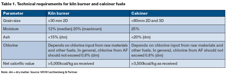
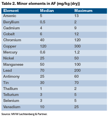
Basic feasibility for new/retrofit handling and storage solutions will require input from a range of partners, including the waste generators, waste management company, local municipalities, AF suppliers and brokers etc. In addition to the above, the feasibility study should also define the technical parameters of the AF (Tables 1 and 2), the operation of the AF facility (layout, mass flow) and the handling and storage capacity needed to support the target TSR. Finally – but most importantly – there will need to be an evaluation of the estimated project investment cost including CAPEX and OPEX, profitability analysis highlighting internal rate of return, net present value and return on investment and free cash flow, and a calculation of potential savings from fossil fuel substitution. “At the end of the day, the choice is always a question of investment and operational cost,” noted Lechtenberg.
Any investment in AF infrastructure should also take into account the fact that the AF space is not static: the availability of fuel types will ebb and flow with developments in the waste management sector. The ideal partner will therefore “deliver systems that can handle different fuel types, giving future flexibility as fuel availability changes,” said Drew.
One developing trend is the use of “increasingly coarse materials, e.g., to feed combustion devices in the calciner,” added Di Matteo. “This has become one of the main directions for our own research and development team in Germany. New methodologies and procedures have been successfully developed through the last few years, and the first installations have now been successfully commissioned.”
The use of AF is also spreading from its original base in Europe to other regions around the world. Each location raises new challenges for the equipment used to handle and store AF. “We were recently involved in realizing the first main burner AF feeding line in Egypt,” continued Dr. Di Matteo. “A decade ago that goal would have been described as impossible due to the difficult material properties and sensitive clinkering process.”
Conclusion
There is no doubt that the handling and storage of AF poses a unique set of challenges for cement plants – especially at plants that are taking their first steps along the fuel substitution road and are inexperienced at handling materials with such potential variability in composition and characteristics. And for all the benefits of taking a holistic approach to systems design and implementation, based on the actual AF material stream, this is not always a realistic option. In this context, the benefits of investing in experienced suppliers and machines, which are designed specifically to handle AF, will almost always outweigh the potential costs.
Our Panel
Dr. Luigi Di Matteo is group CEO, Di Matteo Group (www.dimatteo.de).
Matt Drew is CEO/UK and group business development manager, Saxlund Group (www.saxlundgroup.com).
Dirk Lechtenberg is managing director, MVW Lechtenberg & Partner (lechtenberg-partner.de).
Alan Highton is national sales manager for Wear Components, Martin Engineering (www.martin-eng.com).